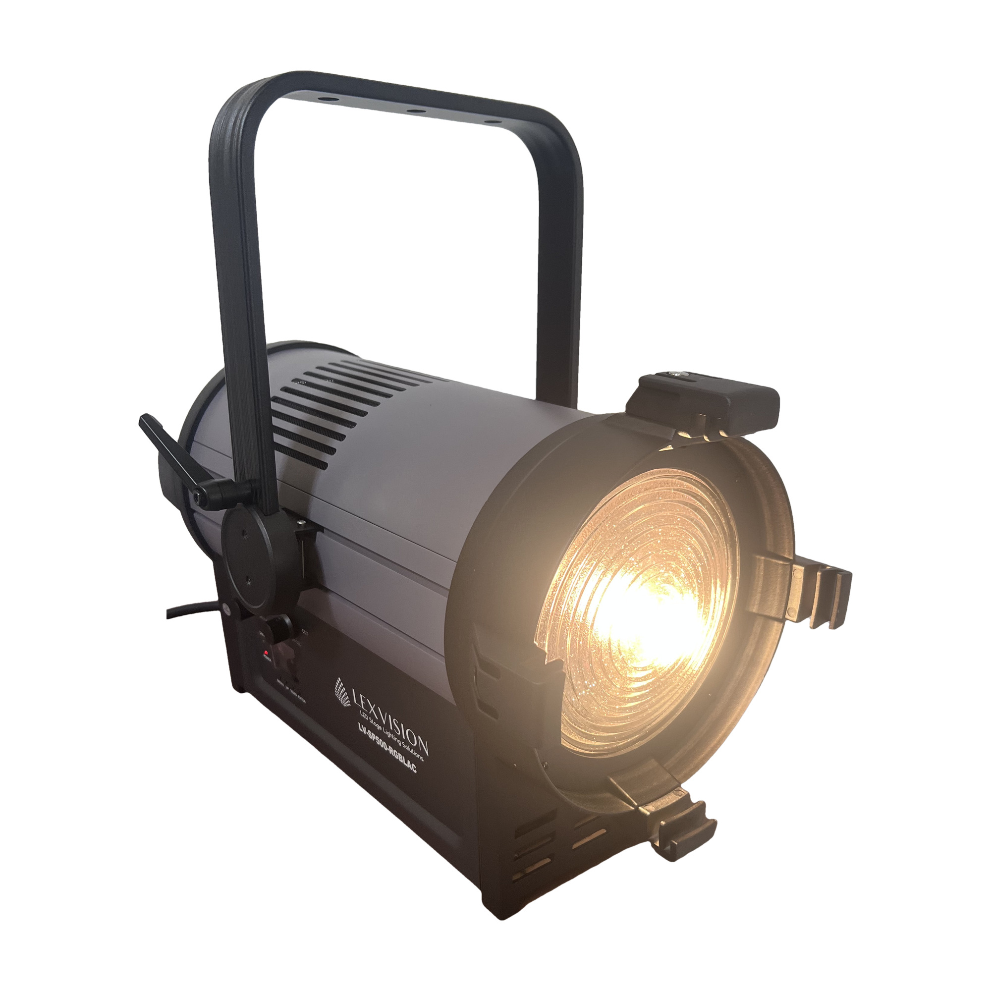
Model LV-SP500-RGBLAC
Edition EN · 09 / 2026 · V2
Document No. LV-SP500-EN-02
RGBLAC 6-in-1 LED Fresnel
LV-SP500-RGBLAC
500 W RGBLAC 6-in-1 COB with motorised auto-zoom 10° – 50°
Operating manual. Please read in full before first use and keep for future reference.
Light source
500 WRGBLAC 6-in-1 COB
Zoom
10° – 50°motorised / auto
DMX
8 / 10 / 12channels · RDM
CRI / CCT
≥ 95
2 000 – 10 000 K
Lexvision LV-SP500-RGBLACForeword · About this document
Foreword
00Welcome
Thank you for choosing the Lexvision LV-SP500-RGBLAC — a powerful LED Fresnel spotlight with a 6-in-1 COB light source and motorised auto-zoom for stage, theatre, studio and events.
This document describes set-up, operation, care and troubleshooting of the fixture. Read the manual — in particular the chapter Safety Instructions — in full before first use and keep it with the fixture. If the fixture is passed on to third parties, the manual must be included.
0.1Symbols used
Warning
Marks situations in which persons may be injured or the fixture may be damaged. Always observe these instructions.
Note
Marks useful additional information, tips or explanations that aid understanding.
Danger — voltage
Marks situations involving danger to life from electric current. Work on live parts is reserved for qualified personnel only.
0.2Intended use
The LV-SP500-RGBLAC is a professional lighting fixture for indoor use on stages, in theatres, in studios and at events. Any other use — in particular outdoors or in humid environments (IP20) — is considered improper and voids the warranty.
0.3Package contents
After unpacking, check the contents for completeness and transport damage.
1 × Lexvision LV-SP500-RGBLAC LED Fresnel
1 × Yoke with quick-lock
1 × Seetronic True power cable (1.5 m)
1 × 8-leaf barndoor
1 × Operating manual
Lexvision LV-SP500-RGBLACContents · Overview
Table of Contents
—Overview
01Safety Instructions04
1.1General safety04
1.2Installation and linking05
02Technical Specifications06
03Controls07
3.1Display, buttons and knob07
3.2XLR pinout (5-pin)07
04Set-up08
4.1Step-by-step set-up08
4.2DMX address calculation08
05Menu Map09
5.1Menu structure09
5.2Settings & dimmer curves10
06DMX Channels11
6.18-CH and 10-CH mode11
6.212-CH mode · CCT · colour macro12
07Troubleshooting13
08Cleaning & Maintenance14
—Quick Reference Card15
—Index16
Lexvision LV-SP500-RGBLAC01 · Safety Instructions
Chapter 01
01Safety Instructions
Read this chapter in full before first use. Damage caused by disregarding these instructions is excluded from the warranty.
1.1General safety
Danger to life from electric current
Before any work on the fixture, the mains supply must be disconnected on all poles and secured against being switched on again. Before connecting, make sure that voltage and frequency of the mains supply match the rating label (AC 100 – 240 V, 50 / 60 Hz).
The protective earth conductor (yellow / green) must be properly earthed to avoid electric shock.
The fixture is intended for indoor use only in dry environments — protection rating IP20. Never expose it to rain, splash water or high humidity.
Install the fixture in a well-ventilated location. Keep a minimum distance of ≥ 51 cm to all adjacent surfaces and do not cover any ventilation slots.
Maximum ambient temperature: ≤ 40 °C (104 °F). Do not operate the fixture above this temperature.
Keep flammable materials (curtains, decoration) away from the fixture — fire hazard.
Never connect the fixture to a dimmer circuit. It must be operated from a direct, non-dimmed power supply.
Use only an undamaged power cable. Never pull directly on the cable.
Do not look directly into the light source during operation — risk of eye damage.
Hot surface & service
The housing heats up during operation. Let the fixture cool down before handling. There are no user-serviceable parts inside — in case of faults, stop operation and contact your dealer. Never repair the fixture yourself.
Lexvision LV-SP500-RGBLAC01 · Safety Instructions
1.2Installation and mounting
The LV-SP500-RGBLAC is mounted to a truss via the quick-lock hook on the yoke. Installation must be carried out by qualified personnel, out of reach of persons and not above walkways.
Risk of falling
The mounting location must safely bear the fixture weight; additionally secure the fixture with a suitable safety cable of sufficient load rating in accordance with local regulations and laws.
Fix the fixture firmly so that it cannot vibrate or slip during operation.
Check all screw and hook connections for tightness before each use.
Ensure adequate ventilation — minimum distance ≥ 51 cm on all sides.
1.3Power linking
Power can be linked through several fixtures via the Seetronic True1 connectors (IN / OUT). Observe the maximum number per circuit — overloading trips the fuse and damages fixtures.
Mains supply
Max. fixtures in chain
Note
220 V AC · 50 Hz
10 fixtures
Use a separate circuit for additional fixtures.
110 V AC · 60 Hz
5 fixtures
Use a separate circuit for additional fixtures.
Note
The fixture must be operated from a continuous, non-dimmed power supply. Even though the dimmer channels allow full 1 – 100 % dimming, the fixture must never be powered via an external dimmer circuit.
Before switching on
Visual inspection for transport damage, loose screws and damage to the power cable.
Set the DMX address and channel mode on the display (see chapters 4 and 5).
Connect to the mains — the power LED lights up as soon as the fixture is correctly powered.
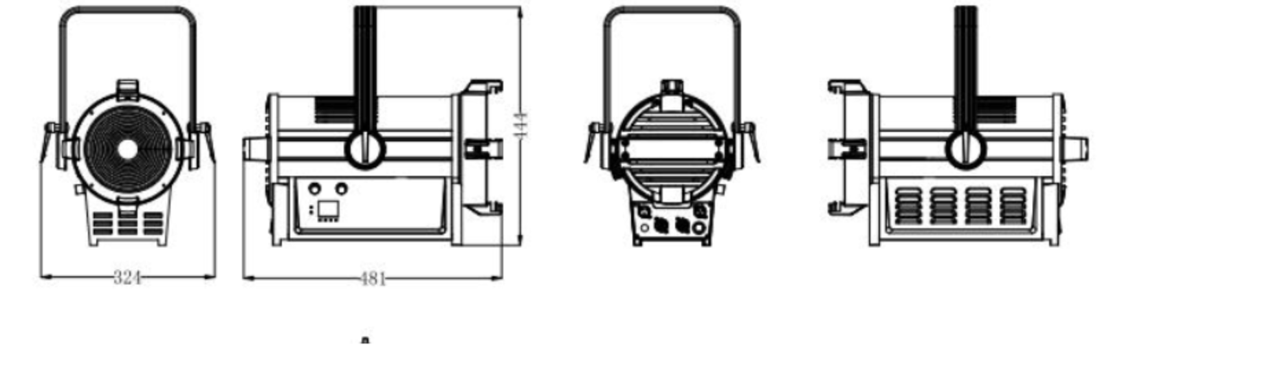
Fig. 2.1 — Front, side and rear view. Dimensions in millimetres: width 324 · length 481 · height 444.
Lexvision LV-SP500-RGBLAC03 · Controls
Chapter 03
03Controls
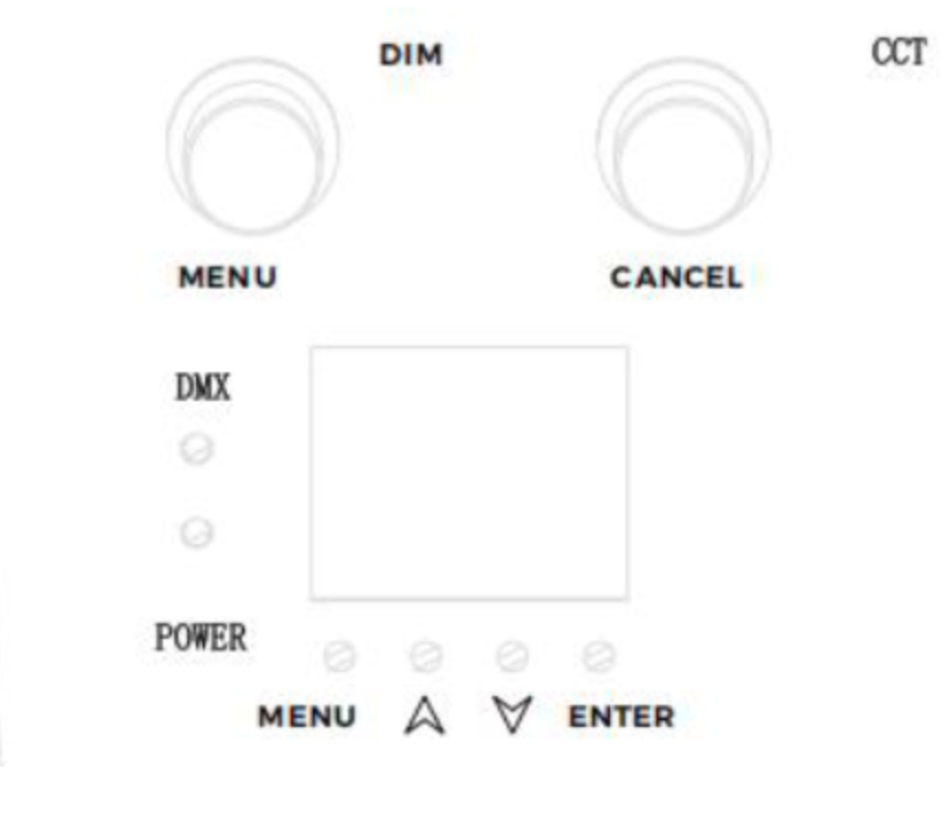
3.1Display, buttons and knob
Menu knob (DIM)Press = confirm, turn = change value/entry
Cancel knob (CCT)Press = back / cancel
LCD displayShows menu level, address and values
DMX LEDFlashes when a DMX signal is present
Power LEDLit continuously when correctly powered
MENU · ▲ · ▼ · ENTERNavigation and confirmation buttons
3.2XLR pinout (5-pin)
The LV-SP500-RGBLAC uses 5-pin XLR sockets for DMX-512. Use only shielded DMX cables (110 Ω) — no microphone cables.
Fig. 3.1 — 5-pin XLR male (DMX OUT)
Pin 1
Shield / GND
Pin 2
Data − (DATA −)
Pin 3
Data + (DATA +)
Pin 4
not used
Pin 5
not used
Note
Fit a 120 Ω terminator on the last fixture in the DMX chain to avoid signal reflections.
Lexvision LV-SP500-RGBLAC04 · Set-up
Chapter 04
04Set-up
4.1Step by step
Unpack and inspectCarefully remove the fixture from the packaging and check for transport damage. Keep the packaging for transport or return shipment.
Choose the mounting locationWell-ventilated location with ≥ 51 cm clearance on all sides. The mounting location must safely bear the fixture weight; additionally secure the fixture with a suitable safety cable of sufficient load rating in accordance with local regulations and laws.
Fit the yoke & secureInsert and lock the quick-lock hook on the truss. Always use a suitable safety cable of sufficient load rating in accordance with local regulations and laws.
Connect the DMX cableConnect the DMX output of the controller to DMX IN; link through to the next fixture via DMX OUT. Terminate the last fixture with 120 Ω.
Connect the power cablePlug in and lock the Seetronic True cable. Observe the maximum number of fixtures per circuit (see 1.3).
Set channel mode & DMX addressPress the knob → “DMX Settings” → select channel mode (8/10/12 CH) and DMX address (1 – 512) (see chapter 5).
Power onOnce power is applied the power LED lights up; the DMX LED flashes when a DMX signal is present. The fixture is ready for operation.
4.2DMX address calculation
Each fixture occupies — depending on the channel mode — a fixed number of consecutive channels. The next fixture starts at start address + channel count. Addresses of the first four fixtures:
Channel mode
Fixture 1
Fixture 2
Fixture 3
Fixture 4
8 CH
1
9
17
25
10 CH
1
11
21
31
12 CH
1
13
25
37
Lexvision LV-SP500-RGBLAC05 · Menu Map
Chapter 05
05Menu Map
Switch on the fixture and press the menu knob to open the menu. Turn the knob to select, press to confirm. Cancel takes you back one level.
5.1Menu structure
Main menu
Sub-menu
Range / options
Default
DMX Address
DMX Address
1 – 512
1
DMX Mode
Channel mode
8 CH · 10 CH · 12 CH
12 CH
Manual Mode
Dimmer
0 – 255
255
Strobe
0 – 255
0
Zoom
0 – 255
255
Red
0 – 255
0
Green
0 – 255
0
Blue
0 – 255
0
Amber
0 – 255
0
Lime
0 – 255
0
CCT
2 000 – 10 000 K
Null
Color Macro
Color 1 – Color 42
Null
Setting
Signal
Clear · Keep
Clear
Backlite
On · Off
On
Display Lock
On · Off
Off
Dimming Curve
Linear · Square · Log · S-Line
Linear
Dimming Hz
2 – 25 K
14 K
Dimming Bit
8 Bit · 16 Bit
16 Bit
Dimming Mode
Stage · Theatre · Meeting
Stage
Fan Mode
Smart · Max · Silent
Smart
Reset / Display Flip
Yes · No
No
Lexvision LV-SP500-RGBLAC05 · Menu Map
5.2Settings in detail
Signal
Behaviour on DMX loss: Clear (off) / Keep (hold)
Backlite
Display backlight on / off
Display Lock
Key lock against accidental changes
Dimming Hz
PWM refresh 2 – 25 kHz (flicker-free for camera)
Dimming Bit
8 / 16 bit dimmer resolution
Dimming Mode
Stage · Theatre · Meeting — characteristic per application
Fan Mode
Smart (regulated) · Max (full cooling) · Silent (quiet)
Reset
Re-initialise the fixture
Display Flip
Rotate display by 180° (overhead mounting)
Color Macro
42 preset colour macros
5.3Dimmer curves
Four dimmer curves adapt the relationship between DMX value and light intensity to the application.
Curve
Behaviour
Mode 1 · Linear
Light output increases linearly with the DMX value.
Mode 2 · Square
Fine steps at low values, coarser at high values.
Mode 3 · Inverse Square (Log)
Coarser steps at low values, finer at high values.
Mode 4 · S-Line
Fine steps at both ends (dark / bright), coarser in the middle range.
Recommendation
For smooth theatre fades use S-Line or Square; for linear console control use Linear. For camera work, match the dimming Hz to the shutter speed.
Lexvision LV-SP500-RGBLAC06 · DMX Channels
Chapter 06
06DMX Channels
6.18-channel mode
CH
Function
Value
Description
01
Red
0 – 255
Red dark → bright
02
Green
0 – 255
Green dark → bright
03
Blue
0 – 255
Blue dark → bright
04
Lime (Lemon)
0 – 255
Lime dark → bright
05
Amber
0 – 255
Amber dark → bright
06
Cyan
0 – 255
Cyan dark → bright
07
Fan Mode
000
Value from display (menu)
001 – 100
Smart (regulated)
101 – 200
Max (full cooling)
201 – 255
Silent (quiet)
08
Focus / Zoom
0 – 255
Narrow (10°) → wide (50°)
6.210-channel mode
CH
Function
Value
Description
01
Dimmer
0 – 255
Dark → bright, continuous
02
Strobe
0 – 255
Slow → fast (0 – 30 Hz)
03
Red
0 – 255
Red dark → bright
04
Green
0 – 255
Green dark → bright
05
Blue
0 – 255
Blue dark → bright
06
Lime (Lemon)
0 – 255
Lime dark → bright
07
Amber
0 – 255
Amber dark → bright
08
Cyan
0 – 255
Cyan dark → bright
09
Fan Mode
0 – 255
As CH 07 in 8-CH mode
10
Focus / Zoom
0 – 255
Narrow (10°) → wide (50°)
Lexvision LV-SP500-RGBLAC06 · DMX Channels
6.312-channel mode
Extended mode with additional CCT and colour macro channel. Recommended for studios and all applications with high demands on colour and white control.
CH
Function
Value
Description
01
Dimmer
0 – 255
Dark → bright, continuous
02
Strobe
0 – 255
Slow → fast (0 – 30 Hz)
03
Red
0 – 255
Red dark → bright
04
Green
0 – 255
Green dark → bright
05
Blue
0 – 255
Blue dark → bright
06
Lime (Lemon)
0 – 255
Lime dark → bright
07
Amber
0 – 255
Amber dark → bright
08
Cyan
0 – 255
Cyan dark → bright
09
CCT
000
No function
001 – 255
Colour temperature 3,000 K → 5,600 K
10
Color Macro
000
No function
001 – 255
Color Macro 1 – 42
11
Fan Mode
0 – 255
Smart / Max / Silent (as 8-CH CH 07)
12
Focus / Zoom
0 – 255
Narrow (10°) → wide (50°)
CCT & Color Macro
CCT (CH 09) mixes a calibrated white temperature of 3,000 – 5,600 K. Colour macro (CH 10) recalls 42 preset colours. Both only take effect when the individual colour channels (R/G/B/lime/amber/cyan) are at 0.
Lexvision LV-SP500-RGBLAC07 · Troubleshooting
Chapter 07
07Troubleshooting
Below you will find solutions to the most common problems. For other faults, contact your dealer or Lexvision service.
7.1Fixture does not respond — no light
#
Check
1
Check the mains connection and main fuse.
2
Measure the mains voltage at the connector (AC 100 – 240 V).
3
Check the power LED on the fixture — if it is not lit, the fixture is not correctly powered.
7.2Fixture does not respond to the DMX controller
#
Check
1
The DMX LED must light / flash. Otherwise check XLR cables and connections.
2
If a channel does not respond: check DMX address and polarity (pin 2 / pin 3).
3
Intermittent dropouts: check the pins on the connectors and on the PCB of the fixture and the preceding one.
4
Test with a different controller to rule it out as the source of the fault.
5
Do not run DMX cables parallel to high-voltage lines — risk of interference.
7.3One channel does not work correctly
The corresponding stepper motor or motor cable may be damaged.
The motor driver circuit may be defective.
Repairs by qualified personnel only
Never attempt to open or repair the fixture yourself. Repairs carried out by unqualified persons can lead to damage or malfunction and void the warranty.